|
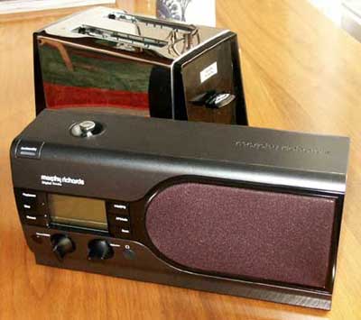
Morphy Richards 27024 together with an old friend (the toaster)
|
|
SOME IMPROVEMENTS ON RECEPTION AND AUDIO QUALITY
|
Morphy works a lot better with an external antenna . . .
|
|
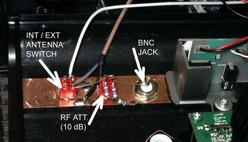
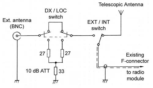
The telescopic antenna in the Morphy Richards is connected via a piece
of coaxial cable to a standard F connector on the radio module. I added
a BNC connector to the rear panel plus two switches, one for switching
between the External Antenna and the Telescopic Antenna and one for the
10 dB RF Attenuator.
|
|
|
Fig. 1
|
|
The modified part with the BNC connector plus two switches, one for
switching between antennas and one for the 10 dB RF Attenuator. A strip
of Scotch copper tape serves as ground.
|
|
|
Fig. 2
|

|
|
|
The Antenna Jack and the switches . . .
|
To the left the Internal/External antenna switch, the 10 dB RF ATT switch and the BNC connector for the External Antenna.
|
|
|
Fig. 3
|
|
The sound from the Loudspeaker could be much better . . .
|
The tweeter which is connected through an chip capacitor (of unknown
value - I lost it when I unsoldered it) does not work, at least it won't
work with that capacitor in series. There is practically no treble
present. Simply short this capacitor by soldering a wire across it. The
tweeter will now be in parallel to the large loudspeaker. Additionally I
stuffed some rock-wool loosely into the cabinet, that improved the
sound even more.
|
|
Still too much bass, too little treble . . .
|
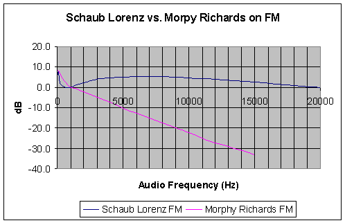
Then I took my vintage ITT Schaub Lorenz Touring T60 from the 1960's
which sounds fine on the FM band. I compared this radio with the AF
output from the Morphy Richards. The frequency response in the Schaub
Lorenz is rather linear from 100 Hz to around 20 kHz. The voltage
across the speaker terminals was about 2.2 V rms without clipping. Doing
the same test with the Morphy proves the listening test: Above 1000 Hz
Morphy has a roll-off of 10 dB / octave which leaves little output of
the higher frequencies.
|
|
Fig. 4
|

|
|
|
The real problem is the response under 1000 Hz . . .
|
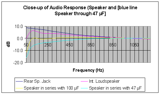
The AM reception on short wave suffers a lot from the increasing
loudness for audio under 1000 Hz. To correct this I tried different
capacitors in series to the loudspeakers. The purple curve is the
original frequency response, the yellow curve shows the response with a
100 uF electrolytic capacitor in series with the loudspeakers and the
light blue curve is the response with 47 uF in series.
|
|
Fig. 5
|
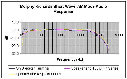
The graph below shows the AM mode Audio Frequency response for the whole
spectrum. It is much better compared to the sound on FM. The spectrum
above 1000 Hz is more or less the same, independent of the size of the
electrolytic capacitor in series with the loudspeakers. The response is
practically linear between 400 Hz and 3600 Hz.
The size of the output capacitor in the speaker circuit doesn't really
matter. 47 uF, 100 uF or no capacitor, it sounds more or less the same.
Only the output voltage differs. The output voltage over the
loudspeaker was 0.9 V rms in the original Morphy, 0.68 V rms with 100 uF
in series and 0.59 V rms with47 uF.
I settled on 100 uF in series with the speakers.
|
|
Fig. 6
|
|
The frequency response in DRM mode . . .
|
The Dream Software can operate as a DRM Transmitter. This, in connection
with my Signal generator Schlumberger Stabilock 4040 created a DRM
Short Wave Transmitter, was at least good enough for testing the Morphy.
I tuned the signal Generator to 7988 kHz. The generator was modulated
in AM mode with the output from Dream set to TX Mode B, 16-QAM /
64-QAM, Protection level 1 und Long Interleaving. In this configuration
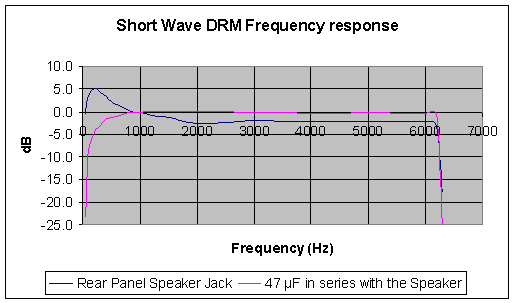
the frequency response was practically linear from 50 Hz to 6000 Hz.
Above 6.2 kHz is practically nothing recordable.
Looking at the output from the signal generator on a HP Spectrum
Analyzer the sidebands with the DRM ± 12 kHz were clearly visible. The
Morphy was tuned to 8000 kHz. The output level from the signal
generator was set to -47 dBm (1 mV in 50 Ohm).
I made two different measurements:
1. On the speaker output jack (3.5 mm Jack) and
2. On the large internal Loudpeaker in series with a 47 µF electrolytic condenser.
The result was positive. The frequency response is perfectly linear.
That means that the reception of DRM signals should be clear and crisp.
However, the Roll-Off on VHF-FM is still a major problem...
|
|
Fig. 7
|
|
The AC Adapter is a terrible source of noise . . .
|
At least the AC-DC power adapter that came with my Morphy generates a
lot of HF energy way up the Shortwave bands, which impairs the reception
considerably. But there is a solution. But you should only try this if
you are well familiar with the handling of equipment meant for 230 VAC
use.
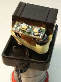
Take a hammer and chisel, break the cover of the AC supply apart, locate
the four rectifier diodes and solder 4 pcs of 10 nF capacitors across
each one of them, then you get rid of a lot of man-made hum and noise!
Almost all the RF buzz and noise from the power adapter disappears! By
the way, the tape inside the adapter was there from the beginning.
|
|
Fig. 8
|

|
As a result, on 30th November 2008, I enjoyed Beethoven' s 9th from
Deutsche Welle on the Morphy Richards in the livingroom running on 230
VAC with the modified AC power supply which came with the receiver and
using its built-in telescopic antenna !
Later in the evening I heard AIR Khampur, Langenberg and RAI on 846 kHz
without problems. Why can't they think of this at the manufacturers?
A lousy AC adapter ruins the reception totally...
|
Dangerous AC adapter!
|
|
Talk about lousy! The other day when I placed the power supply into the
230 VAC wall socket, the connector pins disappeared into the adapter.
After opening the adapter I saw the 230 VAC pins both 0.5 mm from the
iron core of the transformer!! Another fraction of a millimeter and the
mains fuse in the house might have blown... Fantastic construction with
all the safey labels on the front. Made in - well, you might already
have guessed - China.
|

|
|
Using a different Power Adapter
|
In March 2009 I tested the original Morphy Richards Power Supply and a different power supply with the following results:
The Original Morphy Richards AC/DC Power Adapter:
(This AC/DC Adapter is not stabilized)
====================================================================
- The adapter only, AC Adapter without load (0.0 A): 12.6 Volts DC
- The adapter connected to the Morphy,
the radio switched off: 10.0 Volts DC at a current of 0.53 A
- The Morphy switched on: 9.6 Volts DC at a current of 0.65 A
Test with a 12 Volt Regulated Power supply:
====================================================================
- Connected to the Morphy, the radio switched off: 12.0 Volts, 0.53 Ampère
- Connected to the Morphy, the radio switched on: 12.0 Volts, 0.65 Ampère
Test with the same Regulated Power supply set to 13.2 Volt:
====================================================================
- Connected to the Morphy, the radio switched off: 13.2 Volts, 0.53 Ampère
- Connected to the Morphy, the radio switched on: 13.2 Volts, 0.65 Ampère
A 10 to 12 Volt Power Adapter with stabilized output and 1 - 1.5 A
capability would be suitable. Be sure that the connector is correctly
polarized! The adapter I have has the "+" pole in the center of the plug
and the outer sleeve is "-". But whatever my advice, I am not taking
any responsibility for what could happen, as I have no schematics for
the Morphy.
|

|
|
Farewell to the Morphy Richards receiver
|
To tell the truth, I got this receiver from RTL more than 10 years ago
in return for helping them with the evaluation of their DRM test
transmissons. I no longer have the receiver. I gave it to someone who
has been to the transmitter site and knows the person I got it from.
Therefore I'm certain that the Morphy is in good hands.
|

Last reviewed on 9th May 2018
|