
|
Fig. 1
The Avion AV-DR-1401 design looks a bit odd.
|
|
On the 29th September 2015 I paid INR 13'605.00 to Avion's bank. That's
what they charged me, 1 radio priced USD 175 + USD 30 for bank charges,
USD 205 in total. After some correspondance I was told that the delivery
would be in October. October came and went and in the middle of
November I was told that they could ship it immediately if I could
provide them with a DHL or FedEx customer number. Finally they mailed
me on the 26th November that the receiver had been shipped to me by
FedEx. The parcel had been picked up from Avion on the 24th and left
for Dubai on the 25th. From there the parcel went to Paris and on the
27th it arrived in Stockholm at 8 in the morning.

|
Fig. 2
The last leg with the Golden Airline FedUpx
|
|
That was on a Friday, so it was delivered on the following Monday around
noon. I paid USD 179 (!) for the shipping plus another USD 62 in
charges and VAT. With a pricetag of total USD 446.- this makes it the
most expensive radio I have bought for the last 35 years!
|
|
FEATURES AND CONTROLS
|
|
The DR-1401 is 280 mm wide, 70 mm deep, 130 mm high and weighs about
1200 gram. I believe the speakers account for almost half the weight! It
came with two remote controls which allows one to be mounted on the
radio itself and the other one can be used to perform all settings from a
distance. On the front there is a multi-purpose knob which can be used
to switch on and off the radio from and to stand-by, to adjust the
volume and to tune the radio. Like the Newstar, the clocking of the
pushbuttons on the remote control seem to be a bit on the slow side, so
one needs to pause when pushing the same button repeatedly (when setting
the frequency). If you press a digit too long you will get a series of
unwanted digits in the display. Some of the buttons on the remote
control have a tendency to bounce, so that you might get 66 instead of 6
when you press the button. Sometimes you don't get anything when a
button is pressed, but that could be because of the slow clocking. The
odd layout of the ten digit keys add to the confusion when selecting
frequencies.
|
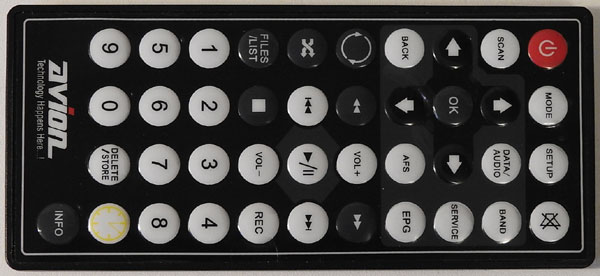
Fig. 3
The Avion Remote Control unit with the odd ten-key layout.
|
|
The radio comes with a built-in 3.7 Volts Li-Polymer rechargeable
battery with 6000 mAh capacity. This allows the DR-1401 to play for up
to 10 hours without an external battery charger. An AC/DC Power Supply
with 5 Volt output is used to charge the DR-1401 from a 230 VAC wall
outlet. The power supply is extremely noisy and you cannot use it when
you want to listen to DRM or AM. It also says so in the User's Manual.
There is a CE mark on it for all it's worth.
The charging time is minimum 5 hours to fully charge the battery. Once
the battery is fully charged, the charging LED will switch from blue to
green colour according to the user's manual. Mine was green all the
time. The reason for this was a production error: Only the green part of
the LED was soldered to the circuit board. The blue LED was either
removed or never soldered.

|
Fig. 4
The lead of the blue part of the LED was not soldered.
|
|
The telescopic antenna is used mainly for the Short Wave and FM
reception. For Medium Wave there is a rather short ferrite Antenna
built into the set. The external antenna jack works well for Medium wave
and Short wave. Both the telescopic and the ferrite antenna seem to be
fairly ineffective. Compared to my other radios there is a big
difference. The reason for this is described further down under
One minor drawback with the LCD Display is that it seems to have been
designed to be looked at from an angle from below rather than from
above. When the radio sits on a table and you look at the display it
tends to be fuzzy. Lean the radio back and the colours come out much
brighter and more colourful. The volume control is in steps, it works
well and there is plenty of power for the two heavy duty loudspeakers.
I started with the radio set to FM mode. The scanning works only on FM
according to the user manual. What happened during the scan was that
the stations it found were added to memory channels, not a scan one by
one. At least it found all the local FM stations very quickly. The
somewhat weaker local FM stations I had to select by their frequencies
and store them manually.
There is no scan function on Medium-, Short wave or DRM. There is no
noise as long there is nothing on the frequency. The speaker is muted.
Selecting a station can be made either using the knob on the front or
to use the numeric keys on the keypad on the remote control. The keys
are prone to bounce, so when you press a digit you may get two digits of
the same in the display and you end up either on the wrong frequency or
on something entirely out of range. Another drawback is when you find a
DRM station in AM mode and you switch to DRM, the frequency is lost. It
is necessary to type in the frequency again to get the DRM station.
Unfortunately for the keen shortwave listener, you can not just press
the knob on the front and turn the knob and tune the band until you hear
a station. When you stop turning the knob for a while the set locks up
on the frequency and if there is a signal stong enough to open the
muting, the AGC starts stepping up gradually and you get sound in the
speakers. If there is nothing on the frequency, you get nothing but
silence. As it is in this firmware version you have to know the
frequency which you want to listen to, tune it and hope that you will be
able to receive it. Some might say that this was not easy and I will
join that club as well. And when you have sound in the speakers and
start turning the tuning knob again, the sound of the previous channel
will play until you stop tuning and then the receiver switches to the
new frequency. There is no way to listen and tune.
The stations can be stored in memory by pressing DELETE/STORE for 3
seconds. Deleting channels can be done the same way. Select a memory
slot and press the DELETE/STORE for 3 seconds and the memory is freed
up. To change to a memory channel just use the LEFT/RIGHT arrow keys on
the Remote Control and press OK. After a short while the radio should
open up and hopefully play.
There is a problem with the memories too. Sometimes when trying to store
a channel is is not possible. Trying to store BBC on 17790 kHz was not
possible. According to Avion this will be solved in the next firmware
release.
Another thing is that the radio won't play for more than an hour at the
time. Suddenly it switches itself off and when this happens no buttons
on the remote control work and you cannot switch the radio on again
without first switch off by using the slide switch and then reboot. In
case you were in the middle of logging a DRM station, there will be
nothing saved to the Micro SD card.
|

|
|
THE LONG AWAITED FIRMWARE UPGRADE
|
What's new?
|
After many promises of a firmware upgrade it finally arrived on the 9th
of April 2016. According to the information I got from the manufacturer
the following has been implemented:
- The DR-1401 now supports multi Multimedia Object Transfer protocol (MOT) on DRM transmissions.
- The signal locking in AM mode is 100 times faster than the previous software.
- The switching between the modes has become more smooth without any obstructions.
- Another licence issue has been resolved so that the receiver won't shut down automatically after 60 minutes.
Perhaps the most interesting news is that the sensitivity and the gain
for the DRM in MW and SW has been increased after a number of rigorous
testing and field trials.
|
|
DRM reception on short wave
|
|
Now, how has this improved the receiver? I must say, unfortunately - not much.
I used the DR111 one morning together with the Avion AVDR-1401, both
sitting on a table using their telescopic antennas and tuned to BBC on
3955 kHz. How do these two now compare? The result? Well, perfect on the
Newstar. The Avion burped twice, that was all. Sorry to say, without an
external antenna the Avion receiver is not possible to use for DRM. And
this after the information I got that the sensitivity on DRM has
improved a lot with the new update.
The same evening I tuned to Voice Of Nigeria on 15120 kHz using three
receivers: My FRG-7700 with its external, active antenna in the garden,
the Newstar DR111 and the Avion AV-DR-1401 both with their built-in
telescopic antennas.
Result:
- FRG-7700 with DReaM: Continuous audio with 22 dB SNR
- Newstar DR111: Continuous audio with 18-19 dB SNR
- Avion AV-DR-1401: The occasional fraction of a second audio burst with MER = 0 tp 7 dBm.
When the Avion AV-DR-1401 shares the external antenna with the Yaesu
FRG-7700: The MER flickered between 13 to 23 dBm and it played with
continous audio. It seems like the telescopic antenna is not working
despite its elaborate antenna amplifiers (or matching circuits?).
|
|
Tuning in AM mode on short wave
|
|
The short wave tuning with the DR-1401 is useless (or at lest very
tiresome) for the everyday short wave listener. Tune into a frequency
and it takes several seconds for the receiver to lock up. When it
eventually does, and there is no transmitter on this frequency, you must
push the tuning knob again and step to the next channel and the same
procedure starts again: Wait for seconds - lock - sound(?), if no sound,
press the tuning knob again. There is not a single signal to hear when
the telescopic antenna is used even if the same signal shows S9+10 dB
on my old FRG-7700. Needless to say, you'd need an external antenna to
get any sound from the speakers in the Avion DR-1401. Perhaps there is
an issue with the telescopic antenna? I will try to find out.
To be fair to Avion, I need to change what I said about the tuning. With
the external antenna connected I discovered that it is possible to tune
into a channel (in 1 kHz steps), wait until the Avion locks to the
frequency (takes a while), and if you don't hear what you like you CAN
continue tuning - IF you do so within 2 (max. 2.5) seconds - otherwise
the DR-1401 locks to the channel and you need to press the tuning/volume
control again.
The muting on short and medium wave has now been deactivated so you can listen for weak signals.
|
Other things that has changed with the new firmware
|
- It looks like the FM reception is better than before, as I can
listen to a local FM station which I could not receive at all before.
The muting on FM seems to be deactivated, or at least the mute treshold
has been lowered.
- In DRM mode I noticed that the display now can show Mode B or C (in the beginning it was only "A" all the time).
Unfortunately, what I thought about the improved sensitivity on FM turned out to be wrong.
|
|
SOME MEASUREMENTS OF THE SENSITIVITY
WITH THE NEW FIRMWARE
|
|
Receiver sensitivity on FM
|
|
it is not possible to connect a signal generator to the Avion in FM
mode, so the output of the signal generator was connected to the
collapsed telescopic antenna, without a ground connection. A signal
level of 250 uV (-59 dBm) was necessary to open the squelch which
(unfortunately) is still in use on FM. This signal level results in a
rather noisy sound in the speakers. The signal strength can be read
from the number of dots in the LCD display.
As a comparison I hooked up the signal generator in the same way to my
National RF-B60. With this receiver, a signal of -87 dBm to produce the
same, slightly noisy audio output from the speaker. That means that my
new Avion radio needs 28 dB more input signal than the 30 year older
National RF-B60 to generate the same output result.
|
|
Receiver sensitivity on Medium Wave (AM)
|
The signal generator was set to 810 kHz and 1000 Hz, 30% AM modulation
and connected to the external antenna socket. A signal level of 10 uV
produces a rather noisy sound in the speakers. 5 uV produces a very
noisy sound in the speakers.
The same signal input method with my old RF-B60 requires a signal of 8
uV to produce the same, slightly noisy audio output and 4 uV for a quite
noisy output.
Result: Both radios seem to perform roughly the same on medium wave.
|
|
Receiver sensitivity on Short Wave (AM)
|
|
On short wave (SW) the signal generator was set to 26.990 MHz and 1000
Hz, 30% AM modulation and connected to the external antenna socket.
Result: Both radios need about 2 uV for a slightly noisy signal.
An attempt to measure the SINAD sensitivity on shortwave in AM mode on
the Avion failed. This was because of the beat tone and noise that is
present on all frequencies.
|
|
Heterodyne interference on Short Wave in AM (and DRM?)
|
|
Initially the frequency was set to 26.995 MHz for the sensitivity
measurement, but there was a rather strong birdie on this frequency and
therefore the SINAD values are affected to the worse. Therefore I
checked more frequencies for birdies. Frequencies such as 4015, 6105,
7330, 9460, 11850, 13510, 15785, 17780, 21540, 25740, 26510 kHz were
chosen at random. All frequencies above 10 MHz are received with a beat
tone which increases slowly in intensity and frequency the higher the
input frequency becomes. The heterodyne stays on the audio output
regardless of the signal strength. Further, a signal stronger than 30 mV
blocks the receiver completely (measured on 21540 kHz). This blocking
level varies slightly with the receiver frequency.
One would probably not hear much of these beat tones when listening to
AM short wave, but, if this kind of instability is present on DRM I
think it would cause problems. That is probably the case, as the SNR
value on DRM rapidly changes from 3 to 25 dB on RRI. Imagine you're
watching an anthill after throwing a stone into it - that is what the
display looks like! The SNR values are crawling around wildly.
|
|
PART 2: NECESSARY MODIFICATIONS
|
SEARCHING FOR THE NOISE THAT THE TELESCOPIC ANTENNA PICKS UP
|
|
The problem: The Class D full bridge audio amplifiers
|
|
After having taken the radio apart I discovered that the telescopic
antenna amplifier output was wired through a switch in the external
antenna jack. Connecting an external antenna disconnects the internal
antennas (on MW and SW) by this antenna jack switch. So why is the
reception so much worse when using the telescopic antenna? I became
suspicious when I got more noise by changing the shield wire's ground
connection. Touching the loudspeaker terminals with a finger or a screw
driver made the noise even worse. With an oscilloscope probe connected
to the speaker terminals I understood that the problem came from there.
There was a 300 kHz square wave about 3.6 Volt p-p present on the
speaker terminals. This explains why there is a shield cover connection
to the chassis of the speakers. The speakers radiate this 300 kHz noise
plus a huge amount of harmonics. As everything on the PCB is covered by
a shield plate it is almost impossible to trace the origin of this
square wave. Without documentation or a schematic diagram one can only
guess that the noise is caused by the class D pulse-width modulated
speaker amplifiers probably designed without low pass filters on their
outputs.

|
Fig. 5
300 kHz square wave with severe ringing on the speaker terminals
|
|
The modification of the speaker outputs
|
|
Unfortunately, the entire PCB is under a shield cover which is soldered
to the PCB (sort of soldered, the production line missed some of the
mounting holes in my receiver), so it is impossible to see what sits
underneath. One of the speaker sockets is located outside the shield, so
I started there. The speaker connector socket was removed and instead
two 68 uH chokes were soldered into the holes with 100 nF (0.1 uF) on
the other side to ground to form a low pass filter. This supressed the
noise a lot. The second speaker connector is hidden under the shield
cover, so the shield of the cable was soldered to the shield case and
the speaker cables were cut as short as possible. Each of the wires
were connected to a low pass filter and the loudspeakers were connected
with unshielded wires.

|
Fig. 6
Low pass filters connected between the amplifier output and the speaker terminals
|
|

|
Fig. 7
Low pass filter circuit diagram (initial circuit)
|
|
In the beginning of July 2016 I noticed in a part of a schematic diagram
I had got hold of that low pass filters actually are present on the
loudspeaker terminals. I have not yet been able to take this part of
the radio to pieces, so I cannot confirm whether my radio belongs to the
lot Rev. A (without low pass filters?) or Rev. B (with low pass filters
as shown in the schematic diagram).
|
|
The sensitivity on AM medium wave and short wave after my modification
|
|
As previously mentioned, an attempt to measure the SINAD sensitivity on
shortwave in AM mode had failed. This was because of the 300 kHz noise
and beat tones that is present on all frequencies above 10 MHz.
Unfortunately, the beat tones are still present on the audio output.
Receiver sensitivity on short wave.
Frequency: 15.665 MHz. 1000 Hz AM with 30% modulation. The signal
generator was connected to the external antenna socket. The result:
- 0.79 uV for 10 dB S+N/N
- 0.84 uV for 12 dB SINAD
Receiver sensitivity on medium wave.
Frequency: 810 kHz. 1000 Hz AM with 30% modulation. The signal
generator was connected to the external antenna socket. The result:
- 4.2 uV for 10 dB S+N/N
- 4.2 uV for 12 dB SINAD
Conclusion:
There was a large improvement on the reception on AM on short wave after
having added the low pass filters to the speaker output terminals.
Before this modification, almost nothing could be received on short or
medium wave using the telescopic antenna.
|
|
The maximum obtainable SINAD on short wave after my modification
|
|
The max. SINAD measured with an RF level around 90 uV was around 19-20
dB on 15.665 MHz and 31.5 dB on 810 kHz. This because there is still a
beat tone superimposed on the audio but most of the noise from the class
D audio amplifiers is gone.
Below is a table with the frequency of the heterodyne tones and the
maximum obtainable SINAD at the same frequencies (medium wave and short
wave). The amplitude of the beat tone is slightly less than 50% of the
wanted AM test tone.
| Beat tones (not a stable tone) | Maximum SINAD |
| 40 Hz | on 500 kHz | 32.5 dB |
| 40 Hz | on 810 kHz | 32.8 dB |
| 28 Hz | on 1440 kHz | 35.2 dB |
| 20 Hz | on 1700 kHz | 35.8 dB |
| 18 Hz | on 3955 kHz | 36.9 dB |
| 25 Hz | on 4500 kHz | 35.5 dB |
| 50 Hz | on 6005 kHz | 31.0 dB |
| 77 Hz | on 7450 kHz | 27.7 dB |
| 83 Hz | on 8000 kHz | 26.0 dB |
| 125 Hz | on 9900 kHz | 24.0 dB |
| 200 Hz | on 15665 kHz | 19.6 dB |
| 222 Hz | on 18000 kHz | 19.4 dB |
| 308 Hz | on 21000 kHz | 17.1 dB |
| 400 Hz | on 26800 kHz | 13.7 dB |

|
Fig. 8
The maximum SINAD values versus the receiving frequency on medium- and shortwave
|
|
MEASUREMENTS OF THE AUDIO FREQUENCY RESPONSE
|
|
The Audio Response was measured with the signal generator set to 30% AM
modulation and the modulation frequency was varied from 100 Hz to 6000
Hz. Two series of measurements were done, one on Medium wave (blue
curve) and the second one on Short wave (red curve). The result is shown
in the graph below.
The audio response is more or less exactly the same on both bands.

|
Fig. 9
The Audio Frequency Response on medium- and shortwave
|
|
The Audio Response on VHF FM was measured with the signal generator set
to 20 kHz FM deviation (that is the maximum I can modulate with the
Stabilock 4040) and the modulation frequency was again varied from 100
Hz to 6000 Hz. The result is shown in the graph below. Above 6000 Hz
there was practically no audio output.
The audio response is more or less exactly the same as for AM on Medium
wave and Short wave, which is a bit puzzling to me. I had thought that
the FM sound quality should be a bit better than what I measured.

|
Fig. 10
The Audio Frequency Response on VHF (FM)
|
|
DRM Audio measurements will follow as soon as I get my little DRM transmitter up and running!
|
Fig. 11
The Audio Frequency Response on DRM (Coming later)
|
|
CAUTION WHEN INSERTING A MICRO SD CARD
|
Problems when a Micro SD memory card is put into the card slot
|
If you insert a formatted Micro SD memory card without any files written
to it there will be problems when you scroll through the menus with the
MODE button on the remote control.
- The radio is switched off by means of the main slide switch on the side of the radio.
- Switch on the power supply.
- Turn on the radio by pressing the button on the remote control or press the volume/on-off knob on the front of the radio.
- It seems like the radio always starts in DRM mode, even if it
was switched off on AM or FM by means of the slide switch on the side of
the radio.
- Press mode from DRM over AM, FM, until the 'MUSIC NOTE' appears in the LCD display.
- Now, the radio does not react to any pushbuttons you press on
the Remote Control. The ON/OFF switch on the front of the DR-1401 does
not work. The only way to solve this problem: Use the slide switch on
the side of the radio to cut the power supply.
- Take out the Micro SD memory card and as a precaution copy a short audio file (mp3 or wav) to the card.
|
The AC power adapter is extremely noisy
|
|
The AC power adapter should be used only to charge the built-in battery
in the receiver. If the radio is swiched on with the power adapter is
connected it is not possible to receive any DRM signals and the short
wave reception suffers badly from the switched power supply. The noise
from this adapter is so strong that it impairs the reception on my
stationary short wave equipment with external antennas too.
|
|
HOW TO CREATE A LOG FROM A RECORDING ON THE MICRO SD CARD
|
Logging DRM with the AV-DR-1401 is possible, but complicated.
|
| 1. | Open Dream Ver. 2.1.1, in Settings and select
- "View Evaluation log"
- "Stations Dialog" |
| 1.1 | Write the frequency you logged in the box below "Target" in Stations Dialog, in this case "17510" |
| 1.2 | In Dream,
click "File - Open File - Files of type = All Files (*)" and locate the
file you want to log, i. e. "17510000_2016-08-25_10-35-05.mdi" |
| 1.3 | Double-click
on the file and check the box "Log to file" in the System evaluation.
Note that only two items are available in the System Evaluation: "Audio
Spectrum" and "SNR/Audio" |
| 1.4 | Let the file play until the end and uncheck "Log to file". |
| 2. | Open the
DRM-Log Plotter and click "Update". Locate the folder with the log
files, normally in the folder where Dream 2.1.1 is located. |
| 2.1 | Double-click on "DreamLog.txt" and next on "DreamLogLong.csv". The log appears in the list box in the DRM-Log Plotter |
| 3. | As the log was recorded earlier, the date and the log start time in DRM-Log Plotter are incorrect |
| 3.1 | Open the DRM Log Editor (DR4MlogEditor303.exe) to edit the date and time
- Click "Load File" in DRM Log Editor. The file you want to edit is the last in the listbox. Click on the Frequency.
- Edit the "New Log Date" and the "New Start Time"
- Click "Modify" and go back to the DRM-Log Plotter and click the "Show Logs" button.
- Click on the log in the listbox. The log plots with the coreect date and time.
|
| 3.2 | As the information in the .mdi file lacks certain data, many labels in the DRM-Log Plotter are empty.
- Only the Decoded Audio is plotted
- There is no SNR, Doppler or Delay in the plot.
|
|
There is still no solution to my problem and at present, February 2019, I
am still waiting for a final answer from Avion how to solve the
problems I experience with this receiver.
|
Latest edit: 23rd Feb. 2019
|
