EH STAR STEP-BY STEP
BUILD THE EH STAR:
WHAT YOU NEED
USEFUL EQUIPMENT
THE SUPPORT
THE WIRING DIAGRAM
WIRING CLOSE UP
THE CYLINDERS
SOLDERING
MOUNTING HOLES
FEED WIRES
PHASING COIL
FINISHED PIPE
COAX SOCKET
COAX WIRES
TUNING COIL FORM
TUNING COIL
FINISHED COIL
TIPS & TRICKS:
FREQUENCY SHIFT
TUNING RANGE
RANGE VS. SWR
USING IT:
ON-AIR TEST
SCREEN SHOT
STABILITY TEST
SUMMARY
SOME THOUGHTS:
THE 3RD ELEMENT
THE 3RD ELEMENT
THE FINAL SOLUTION
BACK TO HOBBY
|
|
BUILD A CB PACKET RADIO EH STAR ANTENNA
IN LESS THAN THREE HOURS
|
|
27 MHz EH-*STAR* - BETTER THAN THE ORIGINAL EH L+L ANTENNA! Step by step instructions.
|
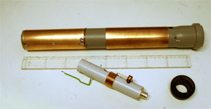
MAIN PARTS FOR THE EH STAR ANTENNA
|
|
This page is a new edition of the original EH STAR page found here earlier. The second EH STAR antenna was based on the instructions on the original EH Star page which has been replaced with this page. The aim was to see how easy it would be to reproduce the EH STAR antenna.
The EH STAR antenna is much easier to build than the L+L antenna, especially nice for beginners. I used a 50 mm grey PP drain pipe according to EN 1451 B or DIN 4102 B1 which I found in the local Do-It Yourself store. Use a rubber reduction fitting for the 50 mm pipe with a 1 1/4 " hole. Fit a piece of 32 mm PVC pipe into the center hole and this pipe supports the tuning coil and the SO-239 coaxial cable connector.
|
|
You would need the following material:
|
- Polypropylene (PP) grey drain pipe, 1 meter length is enough, 50 mm outer diameter
- PVC installation pipe, one 3 meter length, 32 mm outer diameter
- A reduction fitting, HT, 50 mm to 1 1/4 " (DN 50 - 1 1/4")
- Copper foil or sheet, 2 pieces 150 mm x 170 mm for the cylinders
- About a meter electrical installation wire, 1,5 mm diameter
- About two and a half meter of 1,32 mm (or 1,0 mm) diameter
enamel insulated copper wire
- One coaxial socket SO-239
- Some selftapping screws 2,5 mm x 5 mm to support the cylinder and fix the Tuning Coil
- Glue or epoxy resin

|
|
Useful equipment:
|
- Transmitter or RF Generator
- SWR Meter
- Vector Analyser (very useful)
- Field Strength Meter
- Grid Dip Meter
- Small vice
- Soldering iron, pliers and wire cutters

|
|
|
Cut the PP drain pipe to a length of 45 cm from the bottom end

|
|
THE PIPE FOR THE ANTENNA IS 45 CM LONG
|
When you have prepared the neccessary parts, it will take about two to three hours to get to the point when you would begin tuning the network.
First, cut a 450 mm long piece of the 50 mm diameter PP drain pipe. Measure from the bottom! Use a pencil to mark the positions for the cylinders. The reference in the list below is from the top of the pipe.
Holes for the phasing coil and the leads to the cylinders will be discussed later.
- The start of the upper cylinder at 5 mm.
- The end of the upper cylinder at 155 mm.
- The start of the lower cylinder at 205 mm.
- The end of the lower cylinder at 355 mm.
- Leaves 95 mm to the bottom end of the pipe.

|

THE EH STAR WIRING DIAGRAM
|

|
The wiring diagram for the EH STAR 27 MHz
The figure to the left shows you the construction of the EH STAR. The red part ist the Phasing Coil, two turns on the PP tube. Note that it is soldered to the upper cylinder, then wound two turns and soldered to the red dotted line, which we would call the Feed Wire. Be sure to run this feed wire as close to the center of the pipe as possible. The blue feed wire runs close to the wall of the pipe and is soldered to the upper edge of the lower cylinder opposite to the connection to the upper cylinder.
These feed wires are discussed below under the title FEED WIRES TO THE CYLINDERS AND CONNECTIONS FOR THE CYLINDERS.
The green part of the coil is the Tuning Coil. It is described below in the text under the headline CONSTRUCTION OF THE TUNING COIL. Note that all coils should be wound in the same direction. The Tuning Coil is just what it says - it resonates on the wanted center frequency, in our case 27.2 MHz. When using enamel insulated 1.32 mm diameter copper wire you would wind 10.5 Turns on the 32 mm PVC pipe. In case of the PVC-insulated electrical installation cable, 1.5 mm in diameter, the number of turns increase to about 11.5 turns.
Note that the lower 5 turns of the Tuning Coil should be closewound, then gradually lose wound. This method makes the final fine tuning much easier. I used a small self-tapping screw to serve as a support for the upper turn of the tuning coil.
The dark green Feed Coil is wound with 1 mm enamel insulated copper wire on an 8 mm coil form. This coil has a ferrite core to adjust its inductance. It is connected to the center connector of the coaxial cable (here the SO-239 coaxial socket) and the other end is connected to a tap at 2 turns from the bottom of the tuning coil. The Feed (or Source) Coil is discussed below under the headline CONSTRUCTION OF THE FEED COIL.
|
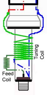
CLOSE-UP VIEW OF THE COILS
|

|
Close-up view of the way of winding the coils
In this drawing the Tuning Coil and the Feed Coil are shown in detail. Notice that the turns of the tuning coil start close wound and then the turns are gradually spread out, making the fine tuning of its center frequency rather easy.
The Feed Coil would have 3 - 12 turns depending of the location of the EH antenna's final location. The purpose of this feed coil is to compensate for any capacitive reactance of the circuit. Tune the feed coil to get the best SWR reading. It should be possible to get a value better than 1.1 : 1 at the antenna's center frequency.
How to arrange the wires connected to earth and to the coaxial connector is discussed in detail further below under the headline THE CONNECTOR WIRES ON THE SO-239.
|
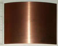
150 mm (H), 180 mm (W)
|
Preparing and mounting of the copper cylinders
Copper sheet can be found in Conrad Electronic (Switzerland, Germany) or in Clas Ohlsson, Insjön (Sweden). Other material like aluminium foil from the kitchen or copper tape (SCOTCH Brand, but rather expensive) can also be used.
Cut two pieces of 0,2 or 0,3 mm thick copper sheet to 150 mm x 180 mm. The thinner sheet is easier to handle. The cylinder height should be 150 mm and the 180 mm leaves some excess copper to overlap allowing to solder the cylinder onto the pipe.
Roll the cylinders onto the 50 mm pipe for starters, then onto the 32 mm pipe to get a good fit for the 50 mm pipe. Watch out for sharp edges! Use gloves when rolling the cylinders.
|
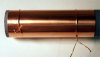

|
Soldering of the copper cylinders
Use some pieces of copper wire to tighten the cylinders to the pipe. Solder the cylinders to fit the 50 mm PP pipe. Start soldering at the top, bottom and in the middle of the cylinders. Finally, solder the entire length of the cylinder.
Make sure that the cylinders are placed at the marks you made and double-check that the distance between the two cylinders is 50 mm (the same as the pipe diameter).
It is essential that the cylinders are fixed on the pipe support. The lower cylinder is supported by its ground feed wire. The upper cylinder needs to be secured by a small short self-tapping screw. Drill a hole through the surface of the upper cylinder and through the pipe and fix the cylinder.
|
|
|
|
The cylinders in place |

|
|
Solder along the entire cylinder
|
|
|
|
The mounting holes on the cylinder pipe
Drill the necessary holes for the phasing coil, the ground (coax shield) and the tuning coil connection. Use a 2,0 mm drill bit for the three holes.
- Drill a hole 5 mm below the upper cylinder. This leaves space for the Phasing Coil.
Drill another hole directly below this hole at a distance of 210 mm. This is the connection of the upper phasing coil to the tuning coil.
- Drill another hole just above the lower cylinder. Be sure to drill this exactly opposite to the hole for the upper cylinder. Drill a corresponding hole directly below this hole at a distance of 165 mm. This is the ground connection to the lower cylinder.

|
|

THE FEED WIRES
|
|
|

|
Feed wires to the cylinders and connections for the cylinders
Connection for the Lower Cylinder:
Cut off a 60 cm long piece and strip from all its insulation. For this you can use 1.5 mm installation wire. Pull this piece of wire by the help of a vice and a pair of pliers to make the wire straight. Bend the wire 90 degrees and bend it again at a distance of 165 mm. Cut the ends so 25 mm remains. Then insert the wire into the pipe and bend its ends on the outside to keep it in place. It should run close to the inner wall of the pipe. Solder it to the top of the lower cylinder. Bend the bottom end downward and cut off leaving 5 to 8 mm.
Connection for the Upper Cylinder:
This wire runs in the center wire of the 50 mm pipe and also supports the phasing coil. Again, use 1.5 mm installation wire. Cut a 60 cm long piece and strip the insulation from both sides so 19 cm remains in the middle. Pull this piece of wire straight by the help of a vice and a pair of pliers. Bend the wire 90 degrees and bend it again at a distance of 210 mm. Cut the ends so that 35 mm remains. Cut two pcs of the insulation you stripped off, each 23 mm long and slip them onto the copper wire. Insert the wire into the pipe and bend its ends, clockwise at the top and downward at the bottom on the outside to keep it in place.
|
|
|

Solder two wires to the center conductor and pull it into place
|
|
|
|
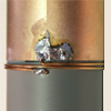
PHASING COIL
|
Winding of the Phasing Coil
Wind the two turn phasing coil clockwise for the upper cylinder from isolated copper wire, in my case 1,32 mm dia. Solder the bare end of the wire to the upper cylinder, wind tightly on the PVC pipe and be sure to keep the coil neat and close to the cylinder. Solder it to the support 5 mm down from the upper cylinder. Cut off the surplus wire, if any.
|
|
|
|
The finished pipe with the cylinders and the phasing coil |

|

|


|
The coax connector for the 32 mm PVC pipe
Cut off a 170 mm long piece of the 3 meter long PVC installation pipe. Put the SO-239 coaxial cable connector on one end of the PVC pipe and mark the edges of the connector. Then, use a small saw or a file and carefully remove the marked areas and continue until the connector can be tightly fitted to the PVC pipe.
|

|
THE GROUND CONNECTOR Solder a lug to the chassis of the coaxial connector SO-239. The lug comes in handy when soldering the 1,5 mm wire for the phasing coil supports later.
|

|
THE CONNECTOR WIRES ON THE SO-239
The RF Connector Wire:
Cut one 10 cm long piece of installation cable. Strip it from all its insulation. Solder it to the center pin of the coaxial connector.
The Earth Connector wires:
Prepare two earth connections, one 12 cm and the other 20 cm long. Leave 50 mm insulation and solder both wires to the solder lug on the coax connector. Push down the insulation towards the solder lug to prevent short circuit with the center lead.
The two longer wires wires will serve as support for the cold end of the tuning coil and to connect earth to the lower cylinder.
|

|
DRILLING OF THE HOLES FOR THE TUNING COIL
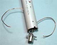
Mark the position for the three holes for the 50 Ω connection and the two earth connectors. One earth serves as the starting point (cold end) of the tuning coil and the other earth will be used to connect earth to the lower cylinder.
Measuring from the bottom of the pipe, mark for holes at 35 mm (Feed Coil connection) and 65 mm (cold end of the tuning coil). Mark the third hole on the opposite side of the pipe at 120mm (the connection to the lower cylinder). Drill all holes with a 2.0 mm bit.
Mark and drill a 2.0 mm hole placed at 115 mm from the bottom roughly at the same side as the 35 and 65 mm position, but on the opposite side on the pipe (the top of the tuning coil to be connected to the upper cylinder). Insert a selftapping screw to serve as a support for the finished tuning coil. If the hole is placed directly above the two holes we would get 10 turns on the coil, but we would like to have 10.5 or so turns.
|
|
MOUNTING THE CABLE CONNECTOR
Now you would fit the coaxial cable connector to the coil form. Feed the coax shield connection wire ("ground") and the 50 Ohm wire connector through the holes in the PVC pipe. Pull the copper wires tightly out through the holes. Check that the SO-239 sits tight in its socket and apply some glue or epoxy to fix it properly. File off the corners of the SO-239 so they do not protrude over the tube.
|

|
Construction of the Tuning Coil
Carefully closewind 13 turns for the tuning coil. This is a suggestion for the 1,32 mm copper wire with enamel insulation. The finished coil would have about 10.5 turns, but the upper few turns should be wound with some space between them. Keep the lower 5.5 turns closely wound.
If you use a different wire diameter, different insulation, different coil form diameter, different spacing between turns, the frequency would change, sometimes dramatically at this rather high frequency. Try to stay close to these recommended values. The top of the upper coil is connected to the feed to the upper cylinder's phasing coil using the excess wire.
CONSTRUCTION OF THE FEED COIL.
The bottom of the tuning coil is connected to the SO-239 ground. The 50 Ohm input is fed to a tap about 2 turns from the cold end of the tuning coil via the feed coil (source coil). The inductance of this feed coil is about a little more than 1 µH. The feed coil is wound with 3 - 14 turns 1,0 mm diameter enamel insulated copper wire on an 8 mm diameter coil form [NOTE 1]. Use an iron powder core to adjust for best SWR while spreading the turns on the tuning coil. The center frequency (best SWR) should fall in the center of the CB Band (channel 20).
NOTE: The number of turns on the feed coil is much depending on the final location of where the EH STAR is mounted. It is better to start with 14 turns, as it is much easier to decrease turns than adding to the coil. If it is not possible to get a good SWR, then decrease to 10, 7 or even less turns for a perfect result.
|

|
CONNECTING THE TUNING COIL AND THE ANTENNA
Detail of the finished tuning coil with its 10.5 turns and the tap at 2 turns from the cold end. Note that the coil is close wound at the bottom and then gradually loose wound towards the top. This allows fine tuning of the center frequency of the antenna.
Press the reduction into the 50 mm pipe and press the 32 mm pipe into the reduction. In case it is difficult to press the pipe into the reduction, spill one or two drops of water into the reduction. The water will dry up and the coil form will sit tight in place.
Use the excess wire from the original 13 turns bent over the screw under the antenna and feed it up to the connection to the phasing coil. On the opposite side, connect the earth to the lower cylinder with a piece of 1.5 mm thick installation wire.
|
|
|
|

|
Elegant solution for a Frequency Shift tuning device
It would be necessary to fix the turns of the tuning coil with glue or epoxy to ensure stability over time and in various climatic surroundings, preventing the turns to change their position.
Tuning the EH STAR in the shack to the exact center frequency could then be a problem. Therefore I tried the effect of a shorted turn of copper wire outside the tuning coil. I had hoped for larger bandwidth, but the result was an elegant method for fine tuning the EH STAR.
I simply used a bobin I found in the gift wrapping paper drawer. Its outer diameter was 42 mm and I fixed it over the tuning coil with three screws at 120 degrees angle. The tuning device consists of one shorted turn of bare copper installation wire, 1.5 mm diameter.
|
|
|

|
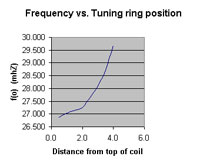
Tuning range
Here we can see the effect of moving the shorted one turn down the bobin. First, tune the EH STAR to a center frequency 0.5 MHz lower than the desired final center frequency. Then, once mounted on the roof, transmit on the desired center frequency and slide the one turn coil slowly downward while observing the SWR meter.
|
|
|

|
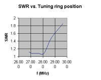
Tuning range and SWR
This diagram shows the SWR over the tuning range when the shorted one turn is moved down the bobin. Between 26.6 and roughly 28 MHz the SWR did not change. From 28 MHz the SWR changes, but the test was made without changing the inductance of the source coil (feed coil).
By decreasing the inductance of the source coil, the SWR was brought down to the same level at 29.5 MHz as for the 27-28 MHz segment as can be seen in the chart.
|
|
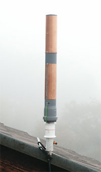
EH STAR
(2x15 cm cylinders spaced 5 cm)

|
A successful test with the second EH STAR
The EH STAR mounted on the roof terrace. After rough tuning on the Antenna Analyser in the shack, there was only a slight change in tuning when it was brought to the roof terrace. A final adjustment to the desired center frequency was easily made by moving the one turn tuning device.
The signal received from the Packet Radio Node HEM550 on mount Rigi 50 km to the southeast from my QTH was measured with two antennas:
The first antenna was a half wave dipole. When substituted with a signal generator, the generator showed +33 dBµV.
The same signal was noted for the EH STAR antenna. Again when substituted with the generator the level showed +33.5 dBµV. Slightly better than the 3.6 meter Vertical.
Again I was able to prove that the EH Antenna when correctly mounted and correctly phased in, the EH STAR compares well to a half-wave dipole.
|

|
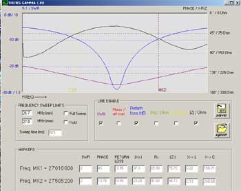
VECTOR ANALYSER SCREEN SHOT
(Screen shot shows Roof Mount results)
LEGEND:
SWR:
Return Loss:
Impedance (Z):
SWR 2 : 1 points:
SWR 1.5 : 1 points
|
Violet
Blue
Black
Lower: 27.016 MHz
Upper: 27.505 MHz
Bandwidth: 489 kHz
Lower: 27.122 MHz
Upper: 27.393 MHz
Bandwidth: 271 kHz
|
| The center frequency was adjusted to 27.235 MHz |
|
|

|
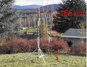
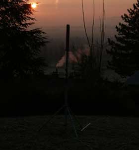
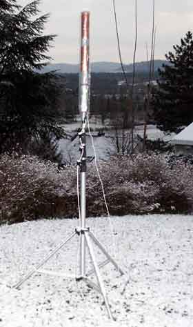
SWR TESTS DURING A WEEK IN THE GARDEN
TEST RESULTS
|
14th Nov. 2004, +2deg. C., cloudy:
26.965 MHz
27.075 MHz
27.205 MHz
27.305 MHz
27.405 MHz
|
SWR:
1.48 : 1
1.32 : 1
1.16 : 1
1.09 : 1
1.15 : 1
|
|
15th Nov. 2004, +0deg. C., partly cloudy:
26.965 MHz
27.075 MHz
27.205 MHz
27.305 MHz
27.405 MHz
|
SWR:
1.45 : 1
1.30 : 1
1.15 : 1
1.09 : 1
1.16 : 1
|
|
16th Nov. 2004, -4deg. C., clear sky:
26.965 MHz
27.075 MHz
27.205 MHz
27.305 MHz
27.405 MHz
|
SWR:
1.52 : 1
1.35 : 1
1.19 : 1
1.07 : 1
1.10 : 1
|
|
17th Nov. 2004, +1deg. C., cloudy:
26.965 MHz
27.075 MHz
27.205 MHz
27.305 MHz
27.405 MHz
|
SWR:
1.32 : 1
1.17 : 1
1.05 : 1
1.10 : 1
1.21 : 1
|
|
18th Nov. 2004, +7deg. C., cloudy:
26.965 MHz
27.075 MHz
27.205 MHz
27.305 MHz
27.405 MHz
|
SWR:
1.34 : 1
1.20 : 1
1.06 : 1
1.10 : 1
1.20 : 1
|
|
19th Nov. 2004, +6deg. C., rain and sleet:
26.965 MHz
27.075 MHz
27.205 MHz
27.305 MHz
27.405 MHz
|
SWR:
1.21 : 1
1.07 : 1
1.05 : 1
1.16 : 1
1.28 : 1
|
|
20th Nov. 2004, +0deg. C., cloudy:
26.965 MHz
27.075 MHz
27.205 MHz
27.305 MHz
27.405 MHz
|
SWR:
1.29 : 1
1.15 : 1
1.05 : 1
1.11 : 1
1.22 : 1
|
|
|
SUMMARY:
The aim of this second antenna was to find out how easy it would be to reproduce it for other antenna builders or experimenters. When I connected the antenna after having put it together and measured it on the Antenna Analyser it proved to satisfy my goal: The antenna resonated at about 27.6 MHz without touching anything.
Pushing the upper turns of the tuning coil closer together moved the center frequency down to 26.6 MHz, which is enough to provide the neccessary tuning range. Therefore it should be possible to fine tune the EH STAR to the desired center frequency even with a SWR meter. An elegant means of tuning the center frequency was also discussed above.
The bandwidth could perhaps be improved. But the bandwidth for SWR 1.5 : 1 is about 27 channels wide and should be of no problem for use with Packet Radio, which is limited to a few channels in the middle of the CB Band.
Some more experimenting with the tuning coil would perhaps result in even better band width. In the meantime I have made improvements on the tap on the Tuning Coil. A tap at one turn from the bottom on the tuning coil improved the bandwidth a little but not dramatically.
This antenna has been in use over a period of time and the reflected power under different weather conditions were recorded. Below is a chart with data taken over a period of one month.
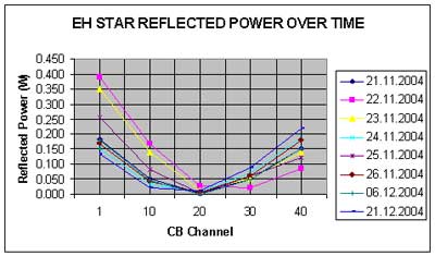
DATA FOR THE EH STAR, MOUNTED ON THE ROOF-TOP TERRACE
The Transmitter RF output power is about 4 Watts

|
|
SOME THOUGHTS ABOUT THE SYSTEM STABILITY OF THE EH STAR ANTENNA
After several tests with the EH STAR I came to the conclusion that the EH STAR needs to be mounted on some sort of a conducting ground plane. This is nothing new, really. Early tests by SM5DAJ pointed towards the need for a good ground at the antenna. It is almost impossible to hang the EH STAR from the ceiling and try to get it to work properly. The whole system is unstable and the coaxial cable is sensitive to the way it is rolled up on the floor, or the SWR changes depending on how the coaxial cable is laid out.
During measurements and tests in the shack, the coaxial socket of the EH STAR was strapped to the corner of a signal generator for practical reasons by means of a small vice. There is simply not enough to have a good earth half a wave length from the transceiver. The instability and the RF along the coax cable disappeared almost completely when the cable connector was in contact with the casing of the signal generator. The size of this third element seems rather uncritical. But it needs to be there. And: The third element and the coax cable do NOT radiate! The radiation maximum is found in the space between the two cylinders.
THE "THIRD ELEMENT"
The "Third Element" has proven to be of great importance. Without the "Third Element", there will be little chance that you will succeed with your EH Star. At least you will have a lot of hassles with instability. The "Third Element" does not radiate. It brings stability into the system. I believe this subject has not been discussed anywhere before.
If you add the "Third Element" as I like to call it, you can stop worrying about:
- All talk about having to use multiple wavelengths of coax to feed the antenna
- The need for the coax to be strung vertically
- Unstable SWR
- Instability due to the way the coax cable is installed
- RF on the feed line

ON POPULAR DEMAND, HERE IS THE STORY BEHIND THE DISCOVERY OF THE "THIRD ELEMENT"

|
Twice in the past I have been asked for help to test commercially made Italian EHA:s (supposed to be EH Stars). The first one I got to investigate was designed for 18 MHz and it was sent to me by an Amateur friend/old colleague. The other was an 11 meter EHA called Aspix 11 which was meant to be used at a 27 MHz Packet Radio Node in Switzerland. Both users wanted to know how you could get these antennas to work properly. Or rather if there was a chance to get them to work as they were supposed to in the reality.
Anyway, the first commercial EH antenna, the one designed for 18 MHz I tested was supposed to be "EH Star". This was before we had discovered that the Italian design differed from the EH Star. It was almost impossible to tune it and it was extremely unstable depending where it was placed, how high over the ground, the way you put the coax cable, all those things I had experienced myself when building my own EH antennas. Later I had to give up this job with the 18 MHz EH Antenna and I sent it back to its owner without doing any more tests.
Then back in November 2005 the importer of the EH antennas in Sweden did not only desperately try to tune them, he finally dismantled one in despair in order to find out why they were so difficult to handle. That was when he found out that the Italian design was different from the original EH Star. The antenna consisted merely of a series coil and a phasing (?) coil which was connected to the upper cylinder. The lower cylinder was connected to the shield of the coax cable connector. The antenna was just a series resonance circuit! This was, according to my opinion, one of the reasons why it did not work very well.
I had always pre-tuned my home made EH antennas in my work shop before mounting them at their final position. I used to hook them to the case of my signal generator at the coax connector of the EHA. Touching the coax after this earth point at the EHA's coax connector posed no problems and the length of the coax cable was no longer critical. This test set-up seemed to be stable. The SWR meter was always inserted at the transceiver antenna socket.
|
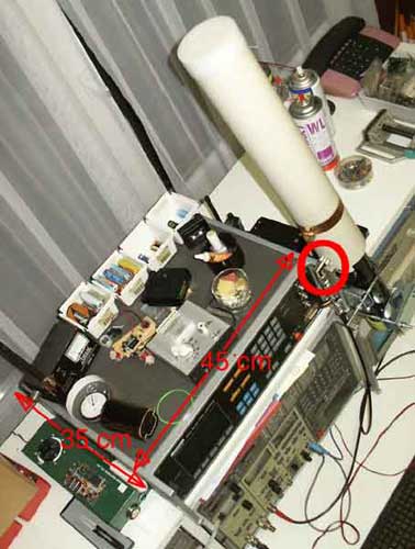
The Aspix 11 on the test bench
|
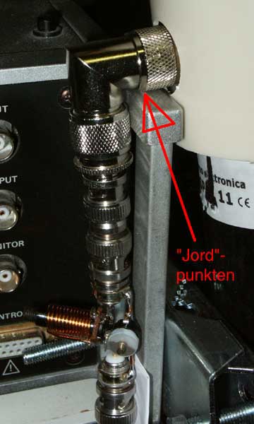
A close-up view of the earth point
|
|
In this configuration my EH Stars were easy to tune and needed only slight retuning on the roof, provided I connected the coax connector of the EHA with a short length of copper wire to a copper sheet on the edge of the roof.
It was when I got the 11 meter Aspix when I more or less by accident found out about the "Magic 3:rd Element". I started measuring the Aspix with a 1/2 wavelength long coax cable between the transmitter and the antenna. The set-up was unstable. The SWR was miserable, 3:1 at 27 MHz. When I touched the coax cable all tuning efforts were upset and the antenna could not be tuned to the wanted frequency either.
Then I placed two 2 meter long aluminium pipes forming a cross (not neccessecarily 90 degrees) on and between some desks in the shack. The crossing point was connected to the coax connector of the Aspix. The cable was connected and ran downward, under the EHA. Now the set-up was stable, but I measured the best (but not very good) SWR at 33 MHz, not 27 MHz. After I had added a coil with 18 turns, 8 mm in diameter the SWR at 33 MHz was 1.1:1 and it was stable.
|
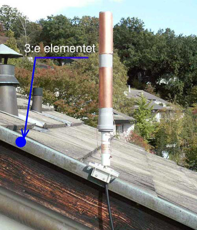
My 27 MHz EH Star and it's "3rd Element"
|
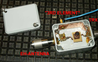
The L/C Filter box for the "Aspix 11"
|
But the 11 meter EHA I got to work fine after I had added a 10-65 pF trimmer capacitor from the coaxial connector conductor to ground. Now it was possible to tune the resonance frequency down to the desired 27 MHz. The bandwidth was around 400 kHz at the SWR 2:1 points. With this L/C network between the coax cable and the EHA coax connector and with the 3:rd element (or ground plane if you so wish) the Aspix worked like a normal EH Star.
|
|
|
I made several tests in my work shop with this "3:rd element". The size of it was uncritical. It just had to be there. The aluminium pipes forming a cross (or any ground plane, one rod, an aluminium plate or my signal generator) seemed to be the solution to get a stable EH Antenna. The crossing point or the ground plane was always connected to the coax connector of the EHA. The coax cable could be placed any way you wanted, and, it did not radiate any RF energy.
|
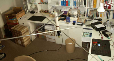
The Aspix 11 mounted on two aluminium tubes
|
When I found out how to get stability into the "Aspix 11" it looked like the picture (left). As you can see, it is not very critical at all how you make the "3rd Element".
|
|
I checked the SWR with different length of coaxial cable, ran part of the cable through a 2 meter long iron water pipe, which I clamped to the cold water pipe in the toilet, fed the another length of cable through a 2 meter long metal pipe, and I wound the coax randomly on the outside of another 2 meter long metal pipe.
|
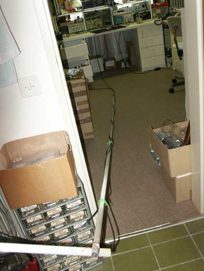
Coax cable wound around and fed through metal pipes
|
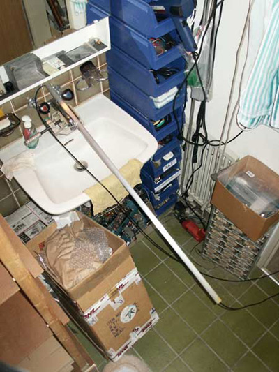
Coax cable through a grounded aluminium pipe
|
|
At last I added a 25 m roll of RG-58 which I just threw into a metal cookie can and observed the SWR after each addition of the cable segments. I could run any length of coax cable around the room on the floor, kick it around, step on it, place metal parts over the cable on the floor. Stable operation under all circumstances.
|
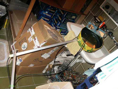
Additional roll of coax cable placed in a metal can
|
|
|
The result: Perfect SWR. Perfectly stable. That was the story of the "Magic 3rd Element".
In the beginning of my tests the connection of the 3rd element was done directly to the coaxial connector of the EHA, but for practical reasons I added an about a meter long piece of wire (the green wires in the picture below) from the coax connector of the EHA to connect to some metal placed somewhere under the EH Star.
|
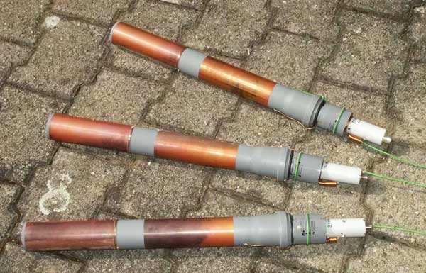
The green wires connect to the 3rd Element
|
Later I made three EH Star for a friend of mine, who wanted to try these on 14, 18 and 21 MHz, all of them complete with a wire to connect a 3rd element, and all three seemed to work well. Here they are pre-tuned for their respective bands.
|
THE 3RD ELEMENT AND THE EH L+L ANTENNA
Just to mention it if someone is curious to know, at the same time I made the tests on the EH Star I also checked the L+L EHA with the 3rd Element, but it did not improve anything or just added to the problems. I had not expected it to work with the L+L type of EHA as it had no earth. In the meantime I have given up on the L+L version.

|
|
(Last update: 11th July 2013. Last reviewed on 6th April 2021)
|
|
 MAIN PARTS FOR THE EH STAR ANTENNA


